Building a Wall Box for Tests A - C
To build a wall box to test for transmit/receive pair continuity and transmit/receive phasing, for test cases A through C, you need the following items:
| • | Insertion tool |
| • | two pieces of #22 AWG wire 8 cm (3 in.) long |
| • | Two wall boxes |
| • | One 1N4001 diode |
| • | Two 47 cm (18 in.) patch cords |
Modify the box as follows:
| 1. | Remove the cover of the wall box. |
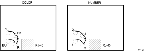
The wall labeling of the insulation displacement terminals on the PC board in the wall box may be either by number or color.
|
Terminal |
Marking Signal |
|---|---|
|
1 or BK |
Transmit (+) |
|
2 or Y |
Transmit (-) |
|
3 or R |
Receive (+) |
|
4 or BU |
Receive (-) |
| 2. | Using the wire insertion tool, connect one of these 8 cm (3 in.) wires from Bk (#1, Tx+) to Y (#2, Tx-). |
| 3. | Connect the other wire from R(#3, Rx+) to BU(#4, Rx-). |
| 4. | With the insertion tool, connect the anode of a diode to BK (#1, Tx+) and the Cathode to R (#3, Rx+). |
Tests A - C for Transmit/Receive Pair Continuity and Phasing
This section details the test procedure for Transmit/Receive Pair Continuity and Transmit/Receive Phasing testing, test cases A through C.
Follow the instructions below to perform the tests:
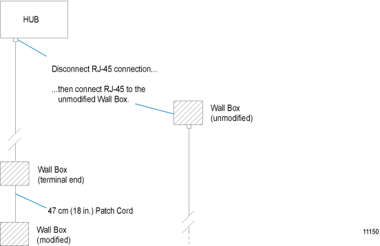
| 1. | Using one of the 47 cm (18 in.) patch cords, connect this modified wall box to the previously installed terminal end wall box of the line you wish to test. |
| 2. | Connect a second wall box (with the cover removed and no wires connected to the insulation displacement terminals) directly to the RJ-45 terminated cable which plugs into the hub at the other end of the line you wish to test. The complete connection should look like that in Figure 3-16. |
| 3. | Determine whether the installation is a 100 percent NCR-recommended Ethernet system or one that uses non-NCR wire and/or equipment. It is necessary to identify the type of Ethernet system since different system configurations have different allowable cable lengths. |
With your ohmmeter in the ohm range, perform the appropriate test below:
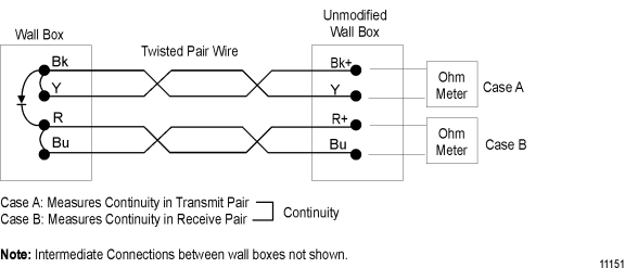
Case A: Tests to measure the continuity in the transmit pair
Measure the resistance between the BK (#1) and Y (#2) terminals at the wall box at the end of the line you are testing.
The resistance levels should be in the range of the table shown in Figure 3-19. Refer to Figure 3-17 for arrangement of wall boxes and ohm meter probes.
Case B: Tests to measure the continuity in the receive pair
Measure the resistance between the R (#3) and BU (#4) at the wall box t the end of the line you are testing.
The resistance values should be in the range of the table shown in Figure 3-19. Refer to Figure 3-17 for the arrangement of wall boxes and ohmmeter probes.
Case C: Test the phasing between transmit pair and receive pair
At the wall box from which you are testing, measure the resistance between BK (#1) and R (#3) with the positive meter probe on the BK terminal. Use the meter to look for the low forward resistance of the diode with this polarity. If a high resistance is observed, the lines are reversed or there is an open line. Resistance level guidelines are not valid when measuring a diode.

|
Wire Type |
Maximum Cable Length |
Max Resistance Per Conductor of 304.8 m (1000 ft) of Cable |
Max Resistance (for Maximum Cable Length) |
|---|---|---|---|
|
AT&T 1061 |
100 m (328.1 ft) |
28.6 ohms |
18.76 ohms |
|
AT&T 1010 |
50 m (164.0 ft) |
28.6 ohms |
9.38 ohms |
|
Other 50 m |
(164.0 ft) |
28.6 ohms |
9.38 ohms |